
This article is a buying guide, but also a comprehensive explanation of various aspects of insulating oil purification machines.
Explaining the equipment’s working principle, oil reclaiming procedures, structure, acceptance criteria, maintenance guidelines, etc.
If you are only looking for useful tips on how to choose a suitable transformer oil purifier for your projects, please jump to Chapter 05.
Table of Contents
Chapter 01: What Is Insulating Oil?
Mineral insulating oil, also called transformer oil, is a kind of petroleum product that often used in high-voltage electrical equipment such as transformers, oil circuit breakers, on-load tap changer,etc.
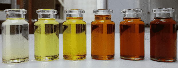
When insulating oil is new, it is a slight yellow liquid, water-like transparent,but the oil color gets yellower and darker as the oil is aging and deteriorating.
Composed of alkanes, cycloalkane saturated hydrocarbons, aromatic unsaturated hydrocarbons and other compounds, there are three main functions of transformer oil, namely, electrical insulation, heat dissipation and arc suppression.
Three main functions of insulating fluids:
- Electrical Insulation.
Insulating oil has a much higher dielectric strength than air. Immersing energized electrical components in insulating oil increases dielectric strength between them. Moreover, oil-immersed electrical parts are also isolated from moisture in the air, preventing oxidation from happening.
2. Heat Dissipation
Insulating oil is also used as coolant. Transformer operation generates heat, which makes the oil near the core and winding to expand and rise in position. Through the up and down flow of insulating oil, the heat is dissipated through the heat spreader to ensure the safe operation of the transformer.
Photo credits: Electrical4u
3. Arc Suppression
The contact switching of energized circuit breaker and on-load tap-changer can generate arcs. Insulating oil helps to suppress an arc quickly.
Chapter 02: Why Does Transformer Oil Need To Be Purified?
The quality of operating transformer oil will gradually deteriorate due to the influence of external impurities and the high operation temperature of the HV electrical equipment itself.
The degraded insulating oil (transformer oil) will not be capable of playing the role of insulation, cooling and arc extinguishing. To ensure the proper operation of power equipment, the transformer oil should be purified regularly.
The purpose of oil treatment is to remove the water, gas and impurities in the oil, improve the electrical strength of the oil, protecting the paper insulation in the oil, and restoring the physical and chemical properties of the oil.
The Source Of Moisture Contamination
- Because most of the power transformers are installed in the open air environment, where insulating oil and atmospheric always have a chance to contact, over time, the moisture in the air gradually invades into the oil from outside.
- The moisture absorbed by cellulose of the insulation material releases into the oil over time.
- Aging cellulose breaks down and also produces trace water into the oil.
Water in oil can be in different forms, Free water(above 200 ppm) or Dissolved Water. Normally, there won’t be so much water inside in-service insulating oil to form free water, so for in-service transformer maintenance, normally only soluble water need to be removed.
However, if needed, centrifuge can be used to for rough cleaning where a large amounts of contaminated oil with high water content need to be handled. Centrifugal separator is the most efficient way to remove free water from oil.
The Source of Air and Gas Contamination
Because the transformer operation generates heat, so the insulating oil inside is subjected to the influence of electricity and heat all the time.
As the temperature rises, methane, ethane, ethylene, acetylene and other gases are gradually produced in the oil.The thermal decomposition of transformer oil starts at about 300℃, and a large amount of acetylene is generated in the arc discharges above 700℃.
The Source of Solid Particulate Contaminants
The impurity particles mixed into transformer oil are mainly fiber, carbon particles and metal impurities, usually from:
- Impurities mixes into the transformer oil during barrel loading and transportation.
- Solid Impurities created in the transformer manufacturing and assembly process. Such as dust pollution in the workshop air,friction scraps and debris during assembling, etc..
Therefore, to ensure the proper operation of an oil-immersed transformer, regular sampling and testing of its in-service insulating oil, regular oil purification practice are all very necessary.
Chapter 03: When Does Your Transformer Oil Need Maintenance Processing?
As time pass by ,Oil keeps deterioration and degradation. The operating oil of distribution transformers has a routine chemical inspection cycle ranging from 1 to 3 years.
Routine test items include moisture, gas content, granularity, acid value, water-soluble acid, flash point, breakdown voltage(BDV), interfacial tension, volume resistivity, color and appearance, etc.
According to the problems reflected by the test results of oil samples, transformer maintenance workers should perform timely insulating oil purification and dehydration in the transformer to avoid transformer failure.
If the power equipment often carries a higher load, then the test intervals should be shortened based on the specified test cycle; If some indicators of the tested items are close to the controlled limit value, the number of tests should also be increased;
Because the quality of the operating oil varies greatly with the aging degree and the different impurities contained, we usually can not rely on a single test item as the basis for evaluating the oil quality. A comprehensive analysis should be carried out according to several main characteristic indicators measured.
Quality of Operating Insulating Oil
| No. | Item | Voltage Grade kV | Quality Index | Methods | |
|---|---|---|---|---|---|
| New Oil | Oil in Service | ||||
| 1 | Appearance | Transparent, no impurities, no suspended solid | visual check | ||
| 2 | Water-soluble acid PH value | ≥5.4 | ≥4.2 | GB/T 7598 | |
| 3 | Acid Number | ≤0.03 | ≤0.1 | GB/T 7599 | |
| 4 | Flash Point | ≥140 | Not 10 lower than new oil | GB/T 261 | |
| 5 | Water content mg/L | 330kV ~ 1000kV 220kV ≤110kV | ≤10 ≤15 ≤20 | GB/T 7600 or GB/T 7601 | |
| 6 | Interfacial tension | ≥35 | ≥19 | GB/T 6541 | |
| 7 | Dielectric loss | 500kV ~ 1000kV ≤330kV | ≤0.007 ≤0.010 | ≤0.020 ≤0.040 | GB/T 5654 |
| 8 | Breakdown Voltage | 750kV~ 1000kV 500kV 330kV 66~220kV 35kV | ≥70 ≥65 ≥55 ≥45 ≥40 | ≥65 ≥55 ≥50 ≥40 ≥35 | GB/T 507 DL/T 429.9 |
| 9 | Volume resistivity | 500kV ≤330kV | ≥6*10 10 | ≥1*10 10 ≥5*10 9 | GB/T 5654 |
| 10 | Gas content | 330kV ~ 500kV | ≤1 | ≤3 | DL/T 423 |
| 11 | Sludge and sediment | <0.02 | GB/T 511 | ||
Chapter 04: What Is a Transformer Oil Purifier?
Transformer oil purifier is an electromechanical equipment that is designed to restore and improve insulating oil’s electrical, chemical and physical properties in a process of vacuum dehydration,degassing and filtration.
The restoration process also removes other degradation products such as soluble polar, volatile acidic, or colloidal materials from used electrical insulating liquids by chemical or adsorbent means.
The transformer oil reclamation plant is suitable for the treatment of new oil and reconditioning of used oil back to a useful state.
Transformer oil purifiers are always evolving and developing. From the 1950s to the 1980s, the treatment of transformer oil in the electric utility industry mainly relied on the pressure filters, also known as Blotter Press or Filter Press.
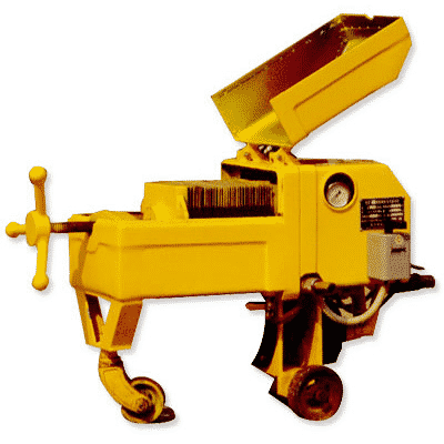
Filter Press uses the pressure of the oil pump to push oil through filter papers, which can remove a limited amount of water contents, particulate impurities, and water-soluble acids from oil by adsorption and filtration so that the transformer oil is purified.
The filter papers need to be dried before use to improve the performance of absorbing water, but since the filter press mainly relied on the filter paper to remove impurities and water content from the insulating oil, it cannot deal with the harmful gases contained in the transformer oil.
However, since the transformer voltage grade was not high at that time, the insulating oil filtered by blotter press could also meet the requirements.
As time goes by, the capacity and voltage grade of electrical transformers continue to raise, the old-fashioned filter press can no longer meet the requirements of the time.
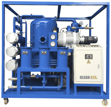
So the vacuum oil purifier is invented, using thermal vacuum treatment techniques, the vacuum oil purifier has a highly efficient dehydrating and degassing capability, which can efficiently remove all form of water contents and harmful gases contained in transformer oil at a comparatively low temperature, 40-60 degrees Celsius.
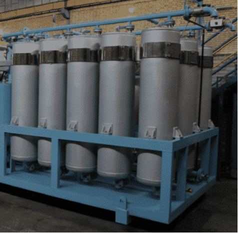
As 750KV, even 1000KV ultra-high voltage transformers are put into use, higher requirements are posed for the performance of transformer oil treatment plants.
Transformer oil processing systems with three-stage or multi-stage vacuum pump combination and finer filtration proficiency have been developed to meet the needs.
Photo credits: transorfilter
Nowadays, most transformer oil reconditioning systems are vacuum dehydrators that adopt thermal vacuum and multi-stage filtration technology.
Chapter 05. How To Choose The Right Insulating Oil Purifier For Your Project?
1. Processing Time
When choosing an oil purification machine, the first thing to be considered is the amount of oil to be treated. The appropriate flow rate of a vacuum oil treatment system is to be able to purify transformer oil in a container for two passes in 8 hours.
For example,
| Oil Amount in Transformer | Suitable Oil Processing Plant Capacity |
| 2400 liter (2.4 tons) | 600 liter/hour |
| 4800 liter (4.8 tons) | 1200 liter/hour |
| 7200 liter (7.2 tons) | 1800 liter/hour |
| 12000 liter (12 tons) | 3000 liter/hour |
| 24000 liter (24 tons) | 6000 liter/hour |
| 36000 liter (36 tons) | 9000 liter/hour |
| 48000 liter (48 tons) | 12000 liter/hour |
| 60000 liter (60 tons) | 15000 liter/hour |
| 72000 liter (72 tons) | 18000 liter/hour |
However, if the moisture and water content of the oil is high, it is recommended to choose a larger insulating oil treatment plant. Higher processing capacity, better purification efficiency.
At the same time, the selection of processing capacity of your oil purifier also needs to consider the time requirement of the on-site transformer maintenance project.
2. Transformer Capacity & Voltage Grade
A compact single-stage vacuum oil filter machine can be used for the maintenance of oil-immersed transformers 66 kV and below.
A double-stage vacuum oil purifier should be used to process insulating oil filled in 110KV electrical equipment above 110kV.
For Generator Step-up Transformers(GSU) above 500kV, a multi-stage Ultra-high Vacuum Transformer Oil Purification Plant should be considered.
| Transformer Voltage Grade | Oil Purifier Vacuum Stage |
| 3kV/6kV/10KV/20kV/35KV/66KV/ | Single-stage Vacuum Transformer Oil Purifier |
| 110KV/220KV/330kV/500kV/ | Double-stage High Vacuum Transformer Oil Purifier |
| 750kV/1000kV/ | Three-stage Ultra High Vacuum Transformer Oil Purifier |
3. Contamination Level Of Oil
If the dielectric liquids to be purified are service-aged oils that has been in operation for many years, with dark color, high acid value and severe dielectric loss, then, you should choose a transformer vacuum dehydrator with oil regeneration columns, in which adsorbent clays (fuller’s earth, activated alumina, molecular sieves) are loaded to remove acids and other oxidation byproducts from oil by percolation method.
4. Work Site Environment
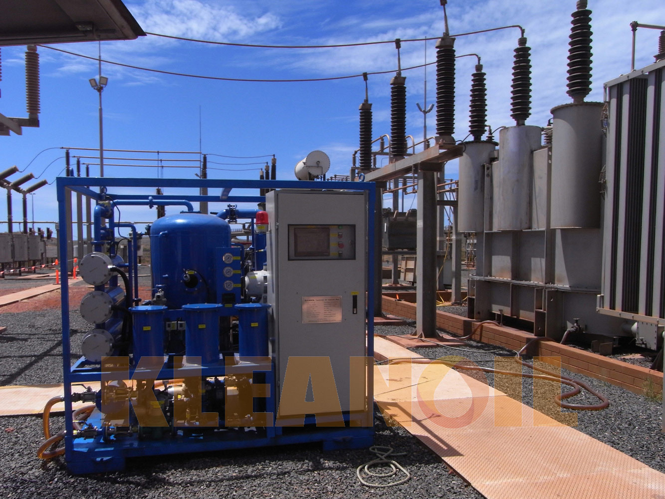
For open field operation projects, it is recommended to choose a mobile oil purifier with weather-proof enclosure. Mounted on a trailer of pneumatic tires, oil filtration machines can travel on an uneven surface with ease, like the gravel ground in an electrical substation yard.
For indoor use, you can choose a skid-mounted oil processing system or vacuum dehydrator with heavy-duty casters, so it can be deployed conveniently on a flat surface. Canopy or housing is optional.
If the oil treatment machine needs to operate in corrosive environment with high humidity, acidic or alkaline,ect, such as on offshore drilling platforms, stainless steel (304,316, 904) needs to be used in fabricating the equipment.
Oil filtration machines with explosion-proof design are mandatory in the presence of flammable or explosive gases, combustible dust or combustible fibers, or any other places with the risk of fire or explosion. For example, petrochemical production and storage environment, underground mining environment, etc.
5. Budgets
When sourcing transformer oil purifiers, customers with a limited budget may consider hire a substation maintenance contractor for on-site services, or rent an insulating oil processing plant from local oil purification companies.
This way, the end-user doesn’t need to own an oil reclamation machine and therefore save the costs of keeping and supporting the equipment.
Chapter 06: Vacuum Transformer Oil Purifier Working Principle
The dehydration and degassing function of the vacuum oil purifier is designed according to the principle of the boiling point difference between water and oil.
Exposed to a high vacuum, the boiling point of water drops significantly, and a large amount of water can be evaporated without a high degree of temperature.
The higher the vacuum degree, the lower the boiling point of water, the faster water evaporation; Also, the higher the temperature, the faster the water evaporates.
But in the transformer insulating oil treatment process, the appropriate temperature range is 50 ~ 60 ℃, preferably not to exceed 65 ℃, to prevent the deterioration of the oil quality due to overheating.
The principle of spray atomization refers to the physical process in which oil is sprayed into the vacuum chamber under pressure so the liquid membrane is broken and the fluid oil is dispersed into tiny oil drops.
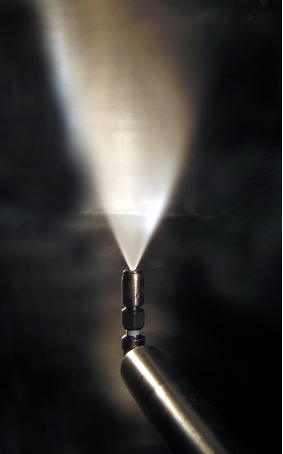
Photo credit:Spray Drying
The process produces a huge number of tiny droplets. When combined, they have a large surface-to-volume ratio, which expands the distribution area of the oil in the vacuum degassing tank.
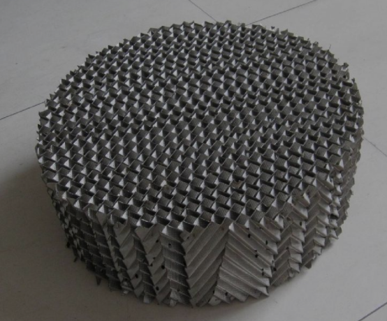
When the insulating oil is injected by the atomization spraying device, it falls slowly to the packed bed layer under gravity. In this process, most of the water and moisture in the oil will be volatilized and discharged by the vacuum system.
At the same time, thin oil films are formed in the packed bed layer, the surface of the oil is enlarged, this process further removes the residual gas and water in oil, improving the degassing and dewatering efficiency.
Packed Bed Function Reference: https://en.wikipedia.org/wiki/Oil_degassing
To remove particulate impurities, the vacuum oil purifier is equipped with a multi-stage filtration system, in which the coarse filter is a strainer installed at the entrance of the oil purification system to remove coarse solid impurities and protect the inlet pump and nozzle.
The secondary filter cartridge is placed after the vacuum chamber to further filter out smaller particulates.
The fine filter element, normally 1 micron, is installed before the oil outlet to ensure that the particulate content of the treated oil is qualified.
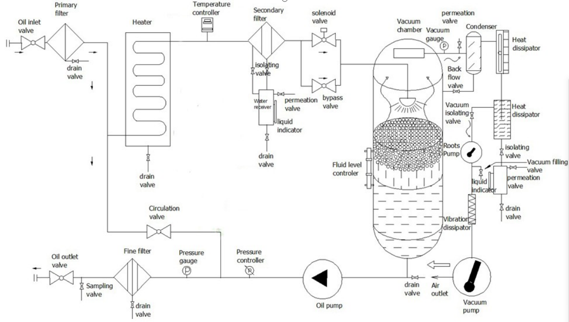
Chapter 07: The Structure Of Transformer Oil Filtration Machine
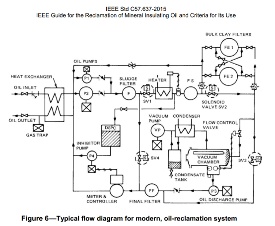
Typical Flow Diagram for Modern Oil Reclamation System
Ref: C57.637-2015 – IEEE Guide for the Reclamation of Mineral Insulating Oil and Criteria for Its Use
The structure of an insulating oil purifier varies from manufacturer to manufacturer but mostly consists of the following major parts: vacuum system, heating system, filtration system, oil transfer system, monitoring system, and control system.
Vacuum separation system: consisting of the vacuum separation chamber, atomizer(sprayer), packed bed, oil gathering tank, defoaming device, auto level control, observation window.
1.Vacuum Chamber: vertical, horizontal, or T-shape container where moisture and gas are separated from heated oil due to thermal degassing & dehydration effect. The larger the vacuum chamber, the better processing efficiency.
2.Sprayer: Atomize the oil entering the vacuum separation tank, the sprayer adopts inverted structure, the oil mist rises first in the degassing chamber and then falls under the action of gravity, therefore, the time the oil is exposed to vacuum is prolonged and the efficiency of dehydration and degassing is enhanced.
3. Packed Bed: To further degas and dehydrate transformer oil, inside the vacuum dehydration chamber, fillers is stacked to form a packed bed, and the oil mist falls onto the packed bed to form an oil membrane, expanding the surface area of the oil, making the water and gases in the oil evaporate more efficiently.
4. Oil Gathering Tank: A structure in which the dehydrated and degassed oil is gathered again and discharged by a drain pump.
5. Automatic Level Control Device: to achieve automatic balance adjustment of incoming and outgoing oil and to provide protection against oil spillage and oil pump idle running.
6. Defoaming Device: For oil that has severe water contamination problems, foam tends to accumulate inside the vacuum chamber. When the foam in the oil is detected by the sensors, the defoaming device will automatically eliminate the foam, thus realizing unattended operation.
7. Observation Window: Tempered glass is used as the observation mirror, which will not be deformed under high temperature and high vacuum conditions.
Heating System:
Equipped with a heating protection mechanism, to prevent heaters from getting burned without flowing oil.
The heating system is interlocked with the vacuum system and oil transmission system, and the heaters can only be switched on after the vacuum pump and oil pump are started,so as to avoid dry burning of the heaters when the oil is still or there is no oil in the system.
The heating system of KLEANOIL oil purifier adopts a grouping design, which can be selected to turn on a single group heater or multiple groups of heaters according to the need.
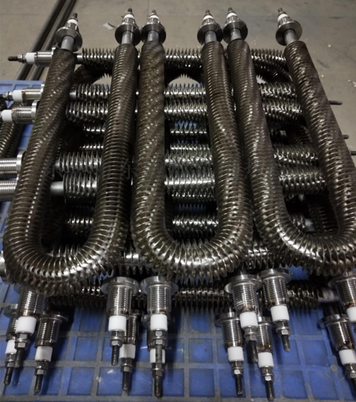
The electric heaters are indirectly heating, the thermal energy of the electric heating wire is transferred to the heater surface through the thermally conductive material.
In order to increase the heat exchange area between the heater and the oil, radiating fins are attached to the heaters to enlarge the surface, and the heater load can be as low as 1.5w/cm² to avoid the insulating oil from cracking and carbonization due to high temperature.
Equipped with a smart thermostat controller, the oil temperature can be easily adjusted。
The optimized piping design ensures smooth oil flow and even heating, and there is no “dead oil zone” in the path of the heating system where oil cannot flow smoothly.
Filtration System
The design and configuration should consider the following factors: filter element precision, BETA value, dirt-holding capacity.
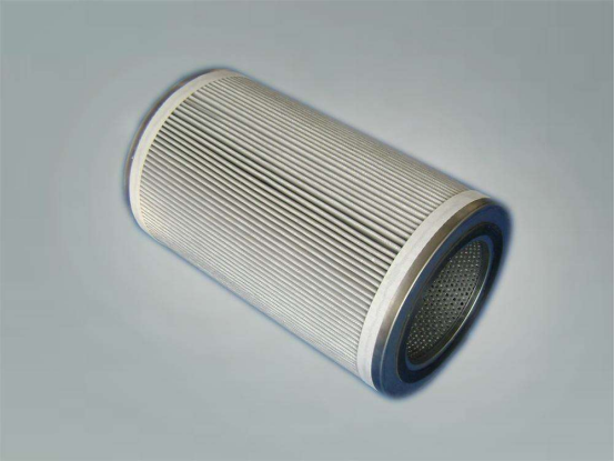
The filtration precision of a filter refers to the maximum particle diameter, measured in microns, that can pass through the filter.
The filter precision is equivalent to the maximum size of the filter pores, and particles larger than this size cannot pass through the filter element and are therefore filtered out.
It reflects the smallest particle size that can be intercepted by the filter, but the particulate contaminants are not all spherical, so there may still be a leak of larger size particles.
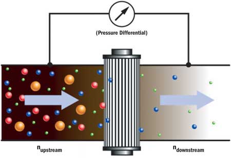
Photo credit: Machinery Lubrication
At present, the most popular indicator to show filtration precision and filtration efficiency is the beta value (β value).
Beta value is a filtration ratio, more precisely, the ratio of the number and sizes of particles contained in the oil upstream and downstream of a certain filter element.
When testing the filtration efficiency of a filter cartridge, first use a particle measuring instrument to examine the number and sizes of impurity particles in a unit volume of oil upstream of the cartridge, then measure the number and size of particles in a unit volume of oil downstream of the cartridge, and then divide the number upstream by the number downstream, and the ratio obtained is the filtration beta ratio (β value).
The larger the β value is, the better the filtration efficiency of the cartridge.
Dirt Capacity( Retention Capacity)
The total amount of contaminants is retained when the pressure drop of the filter element reaches the specified limit pressure drop.
According to ISO4572 standard, the weight of particles captured on the filter material per unit area (mg/cm2) when the pressure difference between the two sides of the filter material reaches 8 times the initial pressure difference.
The larger the dirt-holding retention capacity is, the better the filter material with the same filtration precision.
Oil Transfer System
Some of the transformer oil filter machines adopt vacuum negative pressure for oil feeding, but for users with oil transfer needs, it’s recommended to choose an oil filtration machine equipped with an independent oil feeding pump, which can conveniently transfer oil from one container to another without starting the vacuum pump system.
KLEANOIL recommends the use of a screw pump as the discharge pump for the oil transfer system of the transformer oil treatment plant. This is because screw pumps have high transfer efficiency, low-pressure pulsation, and stable transfer flow. Moreover, the screw pump has strong self-priming capability, low working noise (about 40 db), and long service life, which are ideal features for transferring insulating oil.
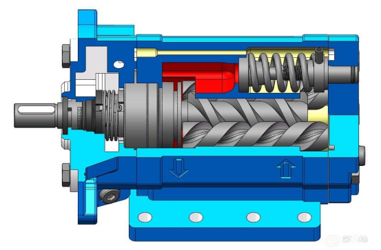
In addition, for transformer oil centrifuging machine, gear pumps are not recommended as oil extraction pump, because under pressure, the bubbles in oil will cause cavitation on the surface of the gears.
The meshing operation of the gears after the damage will generate high temperature, hundreds of degrees Celsius high, which in turn will destroy the oil film and cause the energy conversion of the bubble-liquid phase change. As a result, the oil will disintegrate and produce acetylene and other harmful gases. The longer the oil filtration process goes, the more serious the gas contamination will be.
Electrical Control System
The oil filtration machine controlled by PLC can operate with one key to start and stop. The operation is fully automatic and unattended. The complete interlock mechanism ensures reliable operation of the machine for long hours.
The oil pump and heaters are interlocked, to ensure that If no flow is detected, the heaters will shut down or be locked.
The vacuum pump and heater are Interlocked: to ensure that the heater can be started only after the vacuum pump starts, and oil is flowing in the heater tubes, to avoid damage to the heaters due to dry burning.
At the same time, if the accumulation of impurities in the filter element reaches a certain extent, the system over-pressure alarm will be triggered, and the warning lamp will light up to indicate filter replacement is needed.
In addition, phase sequence protection, overload protection, automatic thermostat system, automatic defoaming mechanism, etc., all combine to guarantee the safe operation of the oil processor in full automation.
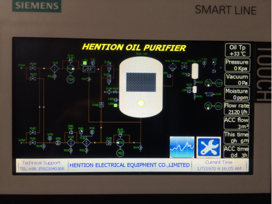
Customers with real-time monitoring needs can choose to equip their oil purifiers with optional online monitoring instruments to monitor the data on HMI screen in real-time.
An online oil moisture transmitter can measure the moisture content in oil during filtration and enable automatic shutdown after the moisture in the oil reaches predetermined requirements.
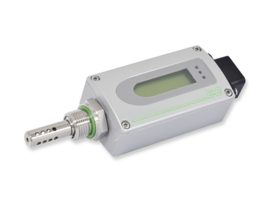
Photo source: E+E
Pirani vacuum gauge can be installed for displaying precise vacuum degrees.
The digital display flow meter can realize automatic shutdown after handling specified oil volume.
The workflow of the vacuum oil filtration machine is as follows:
Insulating oil is drawn into the processing system and is passed through the primary filter by the negative pressure created by the system’s vacuum pump. Then the oil flows through the heaters, during which the oil temperature is raised to a preset degree.
After passing the secondary filter, the heated oil then enters into the vacuum chamber, where water and gasses contained in the oil are thoroughly exposed to vacuum by efficient dispersion and removed through vacuum pumping.
KLEANOIL oil purification system uses a sprayer inside the vacuum chamber for the maximum exposure of oil to the effect of vacuum. The sprayer has great efficiency in breaking oil into tiny droplets, thus greatly improve dehydration and degasification.
The oil is then discharged by an oil pump through a high-efficiency filter element where a fine polishing of oil takes place. After passing through the Fine Filter, the purified oil exits through the outlet or flows via the recirculation valve to be processed again.
Chapter 08: Main Functions Of Vacuum Transformer Oil Purifier
Vacuum Oil Drying and Degassing
Under the influence of the thermal electric field, oil in contact with oxygen is gradually oxidized to generate various kinds of oxides, forming insoluble colloids and sludge precipitates.
These oxides acids further reduce the insulating properties of the transformer oil.
Vacuum oil purifiers remove dissolved gases and dissolved water from insulating oil, preventing the formation of oxides such as colloids and sludge in the transformer oil, thus improving dielectric strength break down voltage.
Precision Filtration
Solid particulate impurities have a significant impact on the dielectric properties of transformer oil.
In the high-voltage electric field, the particles will form “bridges”, forming a weak link in the insulation, reducing the insulation properties of transformer oil and leading to insulation breakdown.
The filtration cartridges of the oil processing system remove all kinds of solid impurities from transformer oil stage by stage to enhance the cleanliness of the oil.
Vacuum Filling of Oil into Transformer
Vacuum oil filling is recommended for topping up power transformers.
First, to perform vacuum evacuation on the transformer to extract residual moisture and air. Transformer vacuum evacuation should not be shorter than 24 hours.
Then, the whole process of oil filling should be kept under vacuum, and oil filling under Vacuum is mandatory for transformers 220 kV and above.
The KLEANOIL transformer oil vacuum degasifier/dehydrator can be switched to vacuum pumping mode and used as a separate vacuum source for oil injection under vacuum.
Hot Oil Circulation
After the transformer oiling is finished, the insulating oil in the transformer body should be circulated with hot oil under a high vacuum (133Pa).
The purpose of flushing the transformer with heated oil is to remove the solid impurities inside the transformer, further bring out the residual water in the core and solid insulation material, and fully take out the dissolved gas in the oil.
For transformers of 220kV and above, After oil filling, hot oil circulation must be performed.
Oil circulation time for 220~330kV transformers should not be less than 24 hours; Circulation time for 500kV transformer and above should not be less than 48 hours.
Oil transfer: A vacuum oil filter machine equipped with an independent oil feed pump can transfer the oil without switching on the vacuum system.
On-site transformer oil processing project
Chapter 09: Acceptance Items And Criteria for Insulating Oil Treatment System
| Type | Items | Criteria | Methods | |
|---|---|---|---|---|
| Double-stage High Vacuum Transformer Oil Purifier | Flow Rate | L/h | Not lower than specified on the nameplate | Test with a flow meter |
| Ultimate Vacuum | Pa | ≤7 | Test with McLeod vacuum gauge after 4 hours of vacuum operation | |
| Working Vacuum | Pa | 133 | Test with McLeod vacuum gauge during oil processing | |
| Vacuum Leakage | Pa*L/s | ≤11 | Refer to Note | |
| Working Pressure | MPa | ≤0.3 | Test with pressure gauge | |
| Noise | dB(A) | ≤83 | Tested according to GB/T 10894 | |
| MTBF | h | ≥4000 | Noted by user during operation | |
| Continuous working period | h | ≥150 | Noted by user during operation | |
| Single-stage Vacuum Transformer Oil Purifier | Flow Rate | L/h | Not lower than specified on the nameplate | Test with a flow meter |
| Ultimate Vacuum | Pa | ≤90 | Test with McLeod vacuum gauge after 4 hours of vacuum operation | |
| Working Vacuum | Pa | ≤666 | Test with McLeod vacuum gauge during oil processing | |
| Vacuum Leakage | Pa*L/s | ≤150 | Refer to Note | |
| Working Pressure | MPa | ≤0.3 | Test with pressure gauge | |
| Noise | dB(A) | ≤83 | Tested according to GB/T 10894 | |
| MTBF | h | ≥4000 | Noted by user during operation | |
| Continuous working period | h | ≥150 | Noted by user during operation | |
Note: Detection Method Of Vacuum Leakage
When the vacuum purifier is under ultimate vacuum, first close the vacuum valve, and stop the vacuum pump, and keep the vacuum for 1 hour, then read the vacuum indicator value of the vacuum meter to calculate the vacuum leakage of the vacuum purifier.
Parameters Of Oil After Treatment
| Type | Items | Criteria | Methods | |
|---|---|---|---|---|
| Double-stage High Vacuum Transformer Oil Purifier | Gas | % v/v | ≤0.10 | DL/T 423 |
| Water | mg/L ppm | ≤3 | GB/T 7600 | |
| Breakdown Voltage | kV | ≥70 | GB/T 507 | |
| Particles NAS | Report | SD/T 313 | ||
| β value | ≥15 | DL/T 423 | ||
| Dielectric loss 90℃ | % | ≤0.50 | GB/T 5654 | |
| Single-stage Vacuum Transformer Oil Purifier | Gas | % v/v | ≤0.50 | DL/T 423 |
| Water | mg/L | ≤7 | GB/T 7600 | |
| Breakdown Voltage | kV | ≥60 | GB/T 507 | |
| Particles NAS | Report | DL/T 423 | ||
| β value | ≥6 | DL/T 423 | ||
| Dielectric loss 90℃ | % | ≤0.50 | GB/T 5654 | |
ASTM Test Methods
| No. | Test Item | Method |
|---|---|---|
| 1 | Color | ASTM D1500 |
| 2 | Visual appearance | ASTM D1524 |
| 3 | Flash point | ASTM D92 |
| 4 | Interfacial tension | ASTM D971 |
| 5 | Pour point | ASTM D97 |
| 6 | Specific gravity | ASTM D1298 |
| 7 | Viscosity | ASTM D445, D2161 |
| 8 | Gas content | ASTM D2945, D3612 |
| 9 | Oxidation inhibitor content | ASTM D4768,D2668 |
| 10 | Water content | ASTM D1533 |
| 11 | Acid number | ASTM D974, D1534 |
| 12 | Oxidation stability | ASTM D2112, D2440 |
| 13 | PCBs in oil by gas chromatography | ASTM D4059 |
| 14 | Dielectric breakdown voltage | ASTM D877, D1816 |
| 15 | Power factor | ASTM D924 |
| 16 | Gas content of cable and capacitor oils | ASTM D831 |
| 17 | Corrosive sulfur | ASTM D1275B |
Chapter 10: Transformer Oil Filtration Plant Maintenance And Trouble Shooting
The safety valve of the vacuum oil purifier has been properly adjusted at the factory, and should not be readjusted under general conditions. If you need to remove it for cleaning, it should be re-calibrated.
When the online transformer oil purification operation is needed, it is recommended to use a steel pipe to connect between the equipment, and the diameter of the oil inlet and discharge pipe must match the output of the oil purifier used.
If a flexible hose is used, the hose should be able to withstand pressure not less than 0.5 MPa.
The machine should be checked routinely to see if:
- a) The electrical control system is safe and reliable;
- b) The temperature controller is sensitive, reliable, and accurate;
- c) Oil seals of the pump shaft are leaking;
- d) There is any blockage inside the unit or any abnormal noise from the pumps or related motors
- e) There is an air or oil leakage from the machine.
When the Inlet Pressure Gauge reaches 0.3Mpa replace the Third Stage Filter. If inlet oil pressure is reduced check and replace the First Stage Filter.
Periodically check oil levels on pumps and refer to the manufacturer’s manuals. Pump oils should be changed if the oil is cloudy or dirty.
If the machine will not be used for more than a month replace the oil in the vacuum pumps. Refer to the manufacture’s recommendation.
Place the machine in a dry environment with the control panel door and all valves closed and protect the machine by covering.
| Faults | Possible Causes | Remedies |
|---|---|---|
| Lack of vacuum | 1. Vacuum pump has problem. 2. Leakage of the machine 3. Vacuum pump oil is insufficient. 4. The vacuum pump oil is polluted. 5. The vacuum gauge has problem | 1. Repair the vacuum pump 2. Locate and fix the leakage 3. Fill oil to recommended level 4. Replace new oil 5. Fix or change |
| VP motor stops suddenly | 1. Motor overloaded 2. The power loss of phase | 1. Check and reset 2. Check the power supply |
| Oil spill out of vacuum pump air vent | 1.Too much lube oil inside the vacuum pump 2.Deforming Solenoid Valve[18] is damaged 3.Forming Detector[20] is damaged 4. Liquid Level Transmitter is damaged | 1. Drain vacuum pump oil to recommended level 2. Fix or change. 3. Fix or change. 4. Fix or change. |
| The quantity of outlet oil reduce, or oil flow stops | 1.The oil level is too low in vacuum tank. 2.High vacuum degree 3.The position of oil container is too high 4. The sealing of oil pump is leaking | 1.Increase the quantity of inlet oil. 2.Reduce the vacuum degree 3.Reduce the height 4. Change oil sealing |
| Inlet oil reduce | 1.First stage filter[03] blockage | 1. Change first stage filter |
| Inlet pressure gauge value increase | 1. Third stage filter[11] blockage. | 1. Change third stage filter |
| Oil temperature doesn’t increase | 1.Temperature sensor has fallen out of its position 2.Heating contactor has problems 3.Wiring termination disconnected 4. Heating element damage | 1.Fasten the temperature sensor 2.Check or change 3.Check and repair 4.Change heater |
| Processed oil is below acceptable standard | 1.There is too much water in oil 2.The oil heating is insufficient 3.The filters are damaged 4.The machine has been contaminated by past uses. 5. The vacuum level is too low | 1. Prolong the processing time 2. Increase the heating temperature 3. Check and change the filter element 4. Clean the machine up 5. See the first item |